Saturday 29 May 2021

Overview of Digital Pulse Modulation Techniques


Overview of Digital Pulse Modulation Techniques

  • All wireless, fiber, and networked digital systems use modulation to encode information onto a carrier signal.

  • As a carrier signal travels through some physical medium, it transports information between endpoints.

  • Digital pulse modulation techniques are a subset of modulation methods for sending digital information over an analog channel.

Datacenter digital pulse modulation techniques

Digital pulse modulation techniques help get data from the cloud onto your smartphone.

You’ll probably never directly interact with digital pulse modulation techniques, but they are pervasive everywhere in modern life. Modulation techniques are responsible for carrying information over long distances in everything from basic radio applications to high speed networking over copper, fiber, and air. Furthermore, without digital modulation techniques, we’d all be stuck using AM and FM radio for wireless communications.

Digital pulse modulation techniques need to be further subdivided into different types in order to better see where each applies in the telecom and networking landscape. As it turns out, digital modulation is not so digital once we start considering multi-level modulation schemes for high data rate channels. If you’ve always wondered how modulation schemes work, keep reading to learn more.

What are Digital Pulse Modulation Techniques?

In the forthcoming discussion, we have to be careful to distinguish between digital pulse modulation techniques and purely digital modulation techniques. These are not always the same thing. In general, these two areas should be carefully delineated as follows:

  • Digital modulation: These schemes use digital data to vary some quality (amplitude, phase, or frequency) of an analog carrier signal. 

  • Digital pulse modulation: These techniques do not use digital signals with constant level for modulation. Instead, pulse modulation involves using quantized pulses to modulate a carrier signal or using a pulse train as the carrier signal for digital data (e.g., PAM4 signaling for high-speed networking). 

The primary difference between these two sets of digital modulation techniques is the use of a truly digital signal vs. the use of pulses in modulation and transmission. Digital pulses do not have constant signal level, in contrast to true digital signals. As a result, digital modulation methods force carrier signal quantities to take specific signal levels. The table below shows a brief comparison of different methods used in each class of modulation methods.


Digital vs. Analog Modulation

There is an important distinction to make between digital methods and analog modulation. In all-analog modulation, the carrier signal and the information-carrying signal are both continuous analog signals. In other words, an analog modulator/demodulator is an all-analog circuit. In contrast, digital pulse modulation and constant-level digital signals give two different ways to quantize analog signals in the time-domain.  

Pulse-Amplitude Modulation

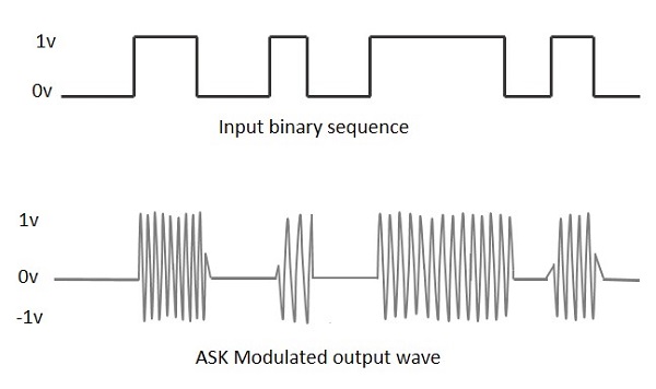
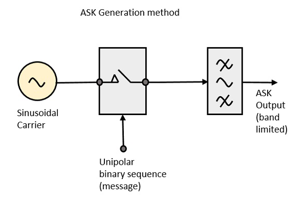
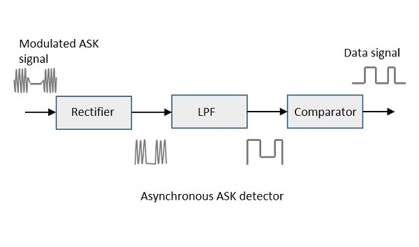
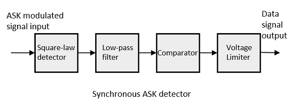
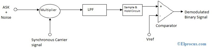
Pulse-amplitude modulation (PAM) is normally described as a purely analog modulation scheme, but this is not exactly true. In some ways, PAM is a fusion between digital, analog, and pulse modulation schemes. In PAM, digital modulation is applied to an analog signal using amplitude shift keying (ASK). This amplitude-modulated analog signal is then used to modulate a pulse train, and the pulse train is sent down a channel. At the receiver end, the signal and data are recovered by sampling the signal at the pulse rate. The reconstructed amplitude-modulated analog signal is then demodulated to recover digital data.

How Does Digital Modulation and Digital Pulse Modulation Work?

Digital Modulation Examples

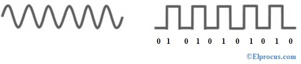
Some examples of digital modulation are shown in the image below. This image shows examples for shift keying methods, specifically phase shift keying (PSK), amplitude shift keying (ASK), frequency shift keying (FSK), and a combination of phase and amplitude shift keying. Similar examples are on-off keying (OOK, where the analog carrier is switched on and off) and non-return to zero (NRZ, just OOK with DC bias).

Digital modulation techniques

Some common digital modulation techniques.

Shift keying methods are simple to use and are ubiquitous in lower-frequency applications involving signal transmission. More advanced methods for high data rate wireless applications and lower-speed fiber have used quadrature amplitude modulation (QAM) with multi-level signaling, where two signals in quadrature (i.e., with a 90-degree phase angle) are used to encode multiple bits of data. When used in radio, the data rate is limited up to 150 Mbps. However, newer optical 64-level dual-polarization QAM (DP-QAM-64) techniques promise up to 600 Gbps data rates down a single fiber.

Digital Pulse Modulation Examples

Digital pulse modulation schemes are effectively the same as analog-to-digital conversion (ADC). In fact, the same digital methods used to modulate an analog signal are used in ADC sampling. Most prominent among these is pulse code modulation (PCM), where an analog signal is represented by a set of quantized digital pulses in the time domain. An analog signal is sampled in the modulator, and the signal level at each sampling interval defines a pulse interval, as shown below.

PCM bit stream digital pulse modulation techniques

PCM encodes analog signal levels as pulses, similar to PAM.

These pulses then propagate down a channel and can be reconstructed at the receiver using a 0th-order hold circuit. The difference between PCM and PAM is that the pulse levels in PCM are quantized, whereas pulses can have any value in PAM (i.e., there is no sampling in PAM). This quantization in PCM and similar sampling methods is what makes these methods digital pulse modulation techniques.

More advanced modulation schemes are making use of multiple carriers (similar to OFDM and QAM) and mixed-signal schemes (e.g., PAM) to carry higher data rates in narrower frequency bands and time windows. A prime example is in 5G, where OFDM, QPSK, and other multi-carrier methods are being used as part of carrier aggregation to provide ultra-high data rates to handsets. It remains to be seen how Ethernet, fiber, and the IEEE 802.3 standards will evolve as more subscribers place greater demands on data centers.

This will likely involve higher resolution PAM methods or some new method for long-distance communication with high bitrate. Whether modulation schemes in future higher bitrate protocols will continue to involve digital pulse modulation is an open question, but it remains an active area of research.

Tuesday 27 April 2021

ASK (Amplitude Shift Keying)

                                                                      ASK.

(Amplitude Shift Keying)

Amplitude Shift Keying (ASK) is a type of Amplitude Modulation which represents the binary data in the form of variations in the amplitude of a signal.

Any modulated signal has a high frequency carrier. The binary signal when ASK modulated, gives a zero value for Low input while it gives the carrier output for High input.

The following figure represents ASK modulated waveform along with its input.

ASK Modulated Waveform

To find the process of obtaining this ASK modulated wave, let us learn about the working of the ASK modulator.

ASK Modulator

The ASK modulator block diagram comprises of the carrier signal generator, the binary sequence from the message signal and the band-limited filter. Following is the block diagram of the ASK Modulator.

ASK Modulator

The carrier generator, sends a continuous high-frequency carrier. The binary sequence from the message signal makes the unipolar input to be either High or Low. The high signal closes the switch, allowing a carrier wave. Hence, the output will be the carrier signal at high input. When there is low input, the switch opens, allowing no voltage to appear. Hence, the output will be low.

The band-limiting filter, shapes the pulse depending upon the amplitude and phase characteristics of the band-limiting filter or the pulse-shaping filter.

ASK Demodulator

There are two types of ASK Demodulation techniques. They are −

  • Asynchronous ASK Demodulation/detection
  • Synchronous ASK Demodulation/detection

The clock frequency at the transmitter when matches with the clock frequency at the receiver, it is known as a Synchronous method, as the frequency gets synchronized. Otherwise, it is known as Asynchronous.

Asynchronous ASK Demodulator

The Asynchronous ASK detector consists of a half-wave rectifier, a low pass filter, and a comparator. Following is the block diagram for the same.

Asynchronous ASK Detector

The modulated ASK signal is given to the half-wave rectifier, which delivers a positive half output. The low pass filter suppresses the higher frequencies and gives an envelope detected output from which the comparator delivers a digital output.

Synchronous ASK Demodulator

Synchronous ASK detector consists of a Square law detector, low pass filter, a comparator, and a voltage limiter. Following is the block diagram for the same.

Synchronous ASK Detector

The ASK modulated input signal is given to the Square law detector. A square law detector is one whose output voltage is proportional to the square of the amplitude modulated input voltage. The low pass filter minimizes the higher frequencies. The comparator and the voltage limiter help to get a clean digital output.


Amplitude Shift Keying (ASK) Working and Applications

The most important and interesting concept in communication is Modulation. It has different types. Modulation is defined as the improving the signal characteristics amplitude, frequency or phase with reference of the carrier signal. If the input signal is analog form then such modulation is called as analog modulation. And if the inputs signal in the form of digital, such modulation is called Digital modulation.  Analog forms of signals are suffered from distortion, noise and interference effects. Due to these three defects, digital signals are preferred than analog. And in digital modulation, the input signal is in the form of digital-only. It has only two voltage levels either high or low. But in the analog signal, its voltage is continued and affected by some type of noise. If the input signal in the form of digital and if you try to increase its amplitude characteristics concerning the carrier signal, this process of modulation is called as Amplitude Shift Keying. It is also known as ASK. This article discusses what is ASK, and its importance.

Amplitude Shift Keying Theory

This type of modulation comes under Digital Modulation schemes. Here, the word keying has some importance, i.e. Keying is indicating the transmission of digital signal over the channel. By the amplitude shift keying theory, we can understand the process of ASK technique.

analog-and-digital-signals

In ASK, it requires two input signals, First input is binary sequence signal and the second input is carrier signal. Here the most important point we need to always consider the second input which is the carrier signal has the more amplitude/voltage range than the input binary sequence signal.

Reason for Choosing the High Characteristics Carrier Signal

For example, if you want to go to someplace you can choose the bus for transportation purpose. Once you reached your destination you come out from the bus. Here when you reached your destination you are not considering the bus which you helped to reach your destination. You are using the bus as just for a medium. So, here also to complete the modulation process, the input binary sequence signal using the carrier signals to reach its destination point.

One more important point is to consider here, the carrier signal amplitude is should be greater than the input binary signal amplitude. Within carrier amplitude range we are going to modulate the binary input signal amplitude. If the carrier signal amplitude is less than the input binary signal voltage, then such a combination modulation process leads to over modulation and under modulation effects. So to achieve perfect modulation carrier single should have more amplitude range than input binary signal.

ask-block-diagram
ask-block-diagram

In amplitude shift keying theory, input binary signal amplitude varies according to the carrier signal voltage. In ASK, the input binary signal is multiplied with the carrier signal along with its time intervals. Between the first time interval of input binary signal multiplied with the first time interval of carrier signal voltage and the same process continues for all time intervals. If the input binary signal is logic HIGH for certain time interval, then the same should be delivered at the output ports with increment in voltage level. So the main aim of the amplitude shift keying modulation is to changing or improving the voltage characteristics of the input binary signal concerning the carrier signal. The below diagram indicating the Amplitude shift keying block diagram.

When the switch is closed – for all the logic HIGH time intervals i.e. when the input signal having logic 1 during those intervals the switch is closed and it is multiplied with the carrier signal which is generating from the function generator for the same duration.

When the switch is opened – when the input signal having logic 0, the switch is opened and there is no output signal will be generated. Because the input binary signal logic 0 having no voltage, so during these intervals when the carrier signal multiples with it, zero output will come. The output is zero for all logic 0 intervals of the input binary signal. Mixer circuit having the pulse shaping filters and band-limited filters for shaping the ASK output signal.

ask-modulation-waveforms

ASK Circuit Diagram

Amplitude shift keying modulation circuit can be designed with 555timer IC as an astable mode. Here, the carrier signal can be varied by using the R1, R2 and C. The carrier frequency can be instantly calculated by the formulae as 0.69*C*(R1+R2). A PIN 4 we will apply the input binary signal and at PIN 3 the circuit will generate the ASK modulated wave.

ask-modulation-circuit

ASK Demodulation Process

Demodulation is the process of reconstructing the original signal at the receiver level. And it is defined as, whatever the modulated signal received from the channel at the receiver side by implementing the proper demodulated techniques to recover/reproduce the original input signal at the output stage of the receiver.

ASK demodulation can be done in two ways. They are,

  • Coherent detection (Synchronous demodulation)
  • Noncoherent Detection (Asynchronous demodulation)

We will start the demodulation process with coherent detection which is also called as synchronous ASK detection.

1). Coherent ASK Detection

In this way of demodulation process, the carrier signal which we are using at the receiver stage is in the same phase with the carrier signal which we are using at the transmitter stage. It means the carrier signal at transmitter and receiver stages are the same values. This type of demodulation is called Synchronous ASK detection or coherent ASK detection.

coherent-ask-detection-block-diagram

The receiver receives the ASK modulated waveform from the channel but here this modulated waveform is effected with noise signal because it is forwarded from the free space channel. So this, noise can be eliminated after the multiplier stage by the help of a low pass filter. Then it is forwarded from the sample and hold circuit for converting it into discrete signal form. Then at each interval, the discrete signal voltage is compared with the reference voltage (Vref) to reconstruct the original binary signal.

2). Non-coherent ASK Detection

In this, the only difference is the carrier signal which is using at the transmitter side and receiver side are not in the same phase with each other. By this reason, this detection is called as Non-coherent ASK detection (Asynchronous ASK detection). This demodulation process can be completed by using with square law device. The output signal which is generating from the square-law device can be forwarded through a low pass filter to reconstruct the original binary signal.

non-coherent-ask-detection-block-diagram

Amplitude shift keying is an effective technique to increase the input amplitude characteristics in communications. But these ASK modulated waveforms are easily affected by noise. And this leads to amplitude variations. Due to this, there will be voltage fluctuations in the output waveforms. The second drawback of the ASK modulation technique is, it has low power efficiency. Because ASK requires the excessive bandwidth. It leads to power loss in the spectrum of ASK.

Whenever to modulate two input binary signals, amplitude shift keying modulation is not preferable. Because it has to take only one input only. So, to overcome this Quadrature Amplitude Shift Keying (ASK) is preferred. In this modulation technique, we can modulate two binary signals with two different carrier signals. Here, these two carrier signals are in opposite phase with 90degrees difference. Sin and cosine signals are used as carriers in quadrature amplitude shift keying. The advantage of this is, it uses effectively the bandwidth of the spectrum. It offers more power efficiency than the amplitude shift keying.

amplitude-shift- keying-matlab-simulink
amplitude-shift- keying-Matlab-Simulink

Amplitude shift keying Matlab Simulink can be designed with Matlab tool. After initializing the tool, by following the proper steps we can draw the ASK circuit on the work area. By giving the proper signal values we can get the modulated output waveforms

ASK Applications

Modulation has an important role in communications. And amplitude shift keying applications are mentioned below. They are:

  • Low-frequency RF applications
  • Home automation devices
  • Industrial networks devices
  • Wireless base stations
  • Tire pressuring monitoring systems

Thus, Ask (amplitude shift keying) is a digital modulation technique to increase the amplitude characteristics of the input binary signal. But its drawbacks make it so limited. And these drawbacks can be overcome by the other modulation technique which is FSK.

Overview of Digital Pulse Modulation Techniques

   Overview of Digital Pulse Modulation Techniques   Author Key Takeaways All wireless, fiber, and networked digital systems use modulation ...